

代码拉取完成,页面将自动刷新
Multiprotocol is a 2.4GHz transmitter which enables any TX to control lot of different models available on the market.
The source code is partly based on the Deviation TX project, thanks to all the developpers for their great job on protocols.
Forum link on RCGROUPS for additional information or requesting a new protocol integration.
To download the latest compiled version (hex file), click on Release on the top menu.
The multiprotocol TX module can be used on any TX with a trainer port.
Channels order is AETR by default but can be changed in the _Config.h.
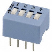
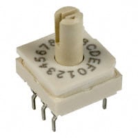
The protocol selection is done via a dip switch, rotary dip switch or scsi ID selector.
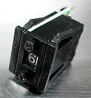
You can access to up to 15 different protocols and associated settings.
Settings per selection are located in _Config.h:
The multiprotocol TX module takes full advantage of being used on a Turnigy 9X, 9XR, 9XR Pro, Taranis, 9Xtreme, AR9X, ... running er9x or ersky9X. An OpenTX version for Taranis is available here.
This enables full integration using the radio GUI to setup models with all the available protocols options.
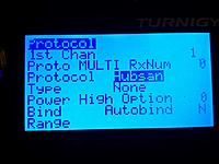
Options are:
Notes:
There are 4 protocols supporting telemetry: Hubsan, DSM, FrSkyD and FrSkyX.
Hubsan displays the battery voltage and TX RSSI.
DSM displays TX RSSI and full telemetry.
FrSkyD displays full telemetry (A0, A1, RX RSSI, TX RSSI and Hub).
FrSkyX displays full telemetry (A1, A2, RX RSSI, TX RSSI and Hub).
Telemetry is available as a serial 9600 8 n 1 output on the TX pin of the Atmega328p using the FrSky hub format for Hubsan, FrSkyD, FrSkyX and DSM format for DSM2/X.
You can connect it to your TX if it is telemetry enabled or use a bluetooth adapter (HC05/HC06) along with an app on your phone/tablet (app example) to display telemetry information and setup alerts.
Telemetry is built in for er9x and ersky9x TXs.
To enable telemetry on a Turnigy 9X or 9XR you need to modify your TX following one of the Frsky mod like this one.
Note: DSM telemetry is not available on er9x due to a lack of flash space.
Enabling telemetry on a 9XR PRO and may be other TXs does not require any hardware modifications. The additional required serial pin is already available on the TX back module pins.
Once the TX is telemetry enabled, it just needs to be configured on the model (see er9x/ersky9x documentation).
The multiprotocol TX module is using a 32bits ID generated randomly at first power up. This global ID is used by nearly all protocols. There are little chances to get a duplicated ID.
For DSM2/X and Devo the CYRF6936 unique manufacturer ID is used.
It's possible to generate a new ID using bind button on the Hubsan protocol during power up.
To bind a model in PPM Mode press the physical bind button, apply power and then release.
In Serial Mode you have 2 options:
Notes:
PPM is only allowing access to a subset of existing protocols. The protocols, subprotocols and all other settings can be personalized by modifying the _Config.h file.
The default association dial position / protocol in every release is listed below.
| Dial | Protocol | Sub_protocol | RX Num | Power | Auto Bind | Option | RF Module |
|---|---|---|---|---|---|---|---|
| 0 | Select serial | ||||||
| 1 | FLYSKY | Flysky | 0 | High | No | 0 | A7105 |
| 2 | HUBSAN | - | 0 | High | No | 0 | A7105 |
| 3 | FRSKYD | - | 0 | High | No | -41 | CC2500 |
| 4 | HISKY | Hisky | 0 | High | No | 0 | NRF24L01 |
| 5 | V2X2 | - | 0 | High | No | 0 | NRF24L01 |
| 6 | DSM | DSM2 | 0 | High | No | 6 | CYRF6936 |
| 7 | DEVO | - | 0 | High | No | 0 | CYRF6936 |
| 8 | YD717 | YD717 | 0 | High | No | 0 | NRF24L01 |
| 9 | KN | WLTOYS | 0 | High | No | 0 | NRF24L01 |
| 10 | SYMAX | SYMAX | 0 | High | No | 0 | NRF24L01 |
| 11 | SLT | - | 0 | High | No | 0 | NRF24L01 |
| 12 | CX10 | BLUE | 0 | High | No | 0 | NRF24L01 |
| 13 | CG023 | CG023 | 0 | High | No | 0 | NRF24L01 |
| 14 | BAYANG | - | 0 | High | No | 0 | NRF24L01 |
| 15 | SYMAX | SYMAX5C | 0 | High | No | 0 | NRF24L01 |
Note:
Serial is allowing access to all existing protocols & sub_protocols listed below.
| Protocol | Sub_protocol |
|---|---|
| Flysky | |
| Flysky | |
| V9x9 | |
| V6x6 | |
| V912 | |
| Hubsan |
| Protocol | Sub_protocol |
|---|---|
| FrSkyV | |
| FrSkyD | |
| FrSkyX | |
| CH_16 | |
| CH_8 | |
| SFHSS |
| Protocol | Sub_protocol |
|---|---|
| DSM | |
| DSM2 | |
| DSMX | |
| Devo | |
| J6Pro |
| Protocol | Sub_protocol |
|---|---|
| Hisky | |
| Hisky | |
| HK310 | |
| V2x2 | |
| YD717 | |
| YD717 | |
| SKYWLKR | |
| SYMAX4 | |
| XINXUN | |
| NIHUI | |
| KN | |
| WLTOYS | |
| FEILUN | |
| SymaX | |
| SYMAX | |
| SYMAX5C | |
| SLT | |
| CX10 | |
| GREEN | |
| BLUE | |
| DM007 | |
| Q282 | |
| JC3015_1 | |
| JC3015_2 | |
| MK33041 | |
| Q242 | |
| CG023 | |
| CG023 | |
| YD829 | |
| H8_3D | |
| Bayang | |
| ESky | |
| MT99XX | |
| MT | |
| H7 | |
| YZ | |
| LS | |
| MJXQ | |
| WLH08 | |
| X600 | |
| X800 | |
| H26D | |
| E010 | |
| Shenqi | |
| FY326 | |
| FQ777 | |
| ASSAN | |
| HONTAI | |
| HONTAI | |
| JJRCX1 | |
| X5C1 |
Note:
Check the Protocols_Details.md file for a detailed description of every protocols with channels assignements.
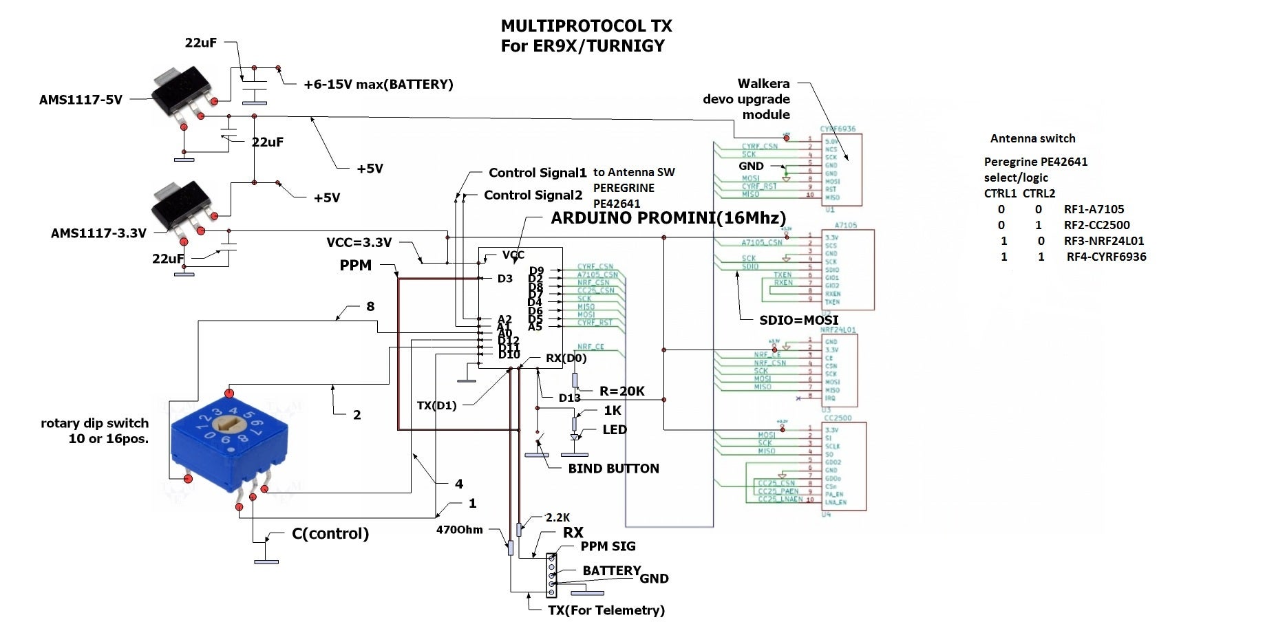
Up to 4 RF modules can be installed:
RF modules can be installed for protocols need only. Example: if you only need the Hubsan protocol then install only a A7105 on your board.
You also need some antennas and cables.
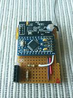
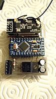
The main program is running on an ATMEGA328p running @16MHz and 3.3V. An Arduino pro mini 16Mhz/5V powered at 3.3V (yes it works) can be used to build your own Multimodule. An Arduino Mini based on Atmega328p can also be used.
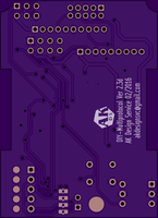
If you build this PCB v2.3c and want to enable serial mode for er9x/ersky9x, you have to do this mod.
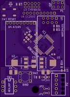
New PCB v2.3d! available
Repository includes Kicad files of schematic and pcb. This is a variant of the Multipro V2.3c circuit design. It is basicly the same as the 2.3c board as far as component placement goes. What's changed is the added resistors for the serial protocol and also the addition of solder jumpers on the bottom of the board for the various options to connect the TX, RX, and PPM lines through them.
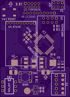
OSH Park link if you want to order.
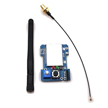
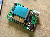
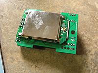
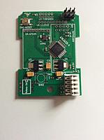
This module can be purchased here. All the 4 RF modules are already implemented A7105, NRF24L01, CC2500 and CYRF6936. The board is also equiped with an antenna switcher which means only one antenna for all.
It is highly recommended to update the firmware of this board as it is distributed with a really old and bugged one. For this you have to solder a 6 pin header (top left) and use an USBASP like explained below.
If you want to enable serial mode for er9x/ersky9x/Taranis/... and depending on your board revision, you have to do one of these modifications:
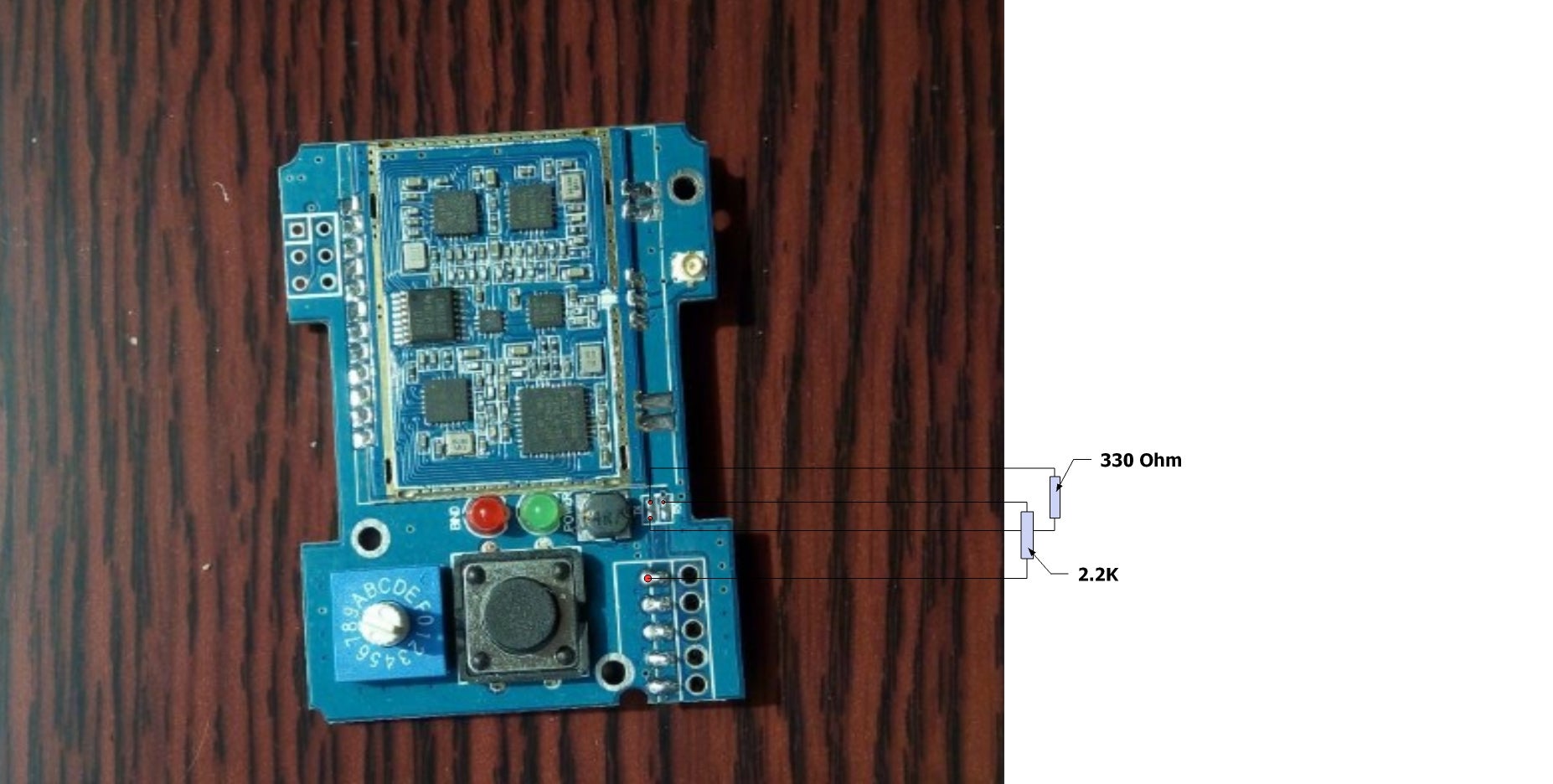

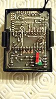
Note: if you have the 1st board revision (check pictures above), sometime bind occures at power up even without pressing the bind button or not having an autobind protocol. To solve this issue, replacing the BIND led resistor (on the board back) of 1.2K by a 4.7K.
Notes:
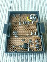
If you build your own version of the board you can 3D print this case (details here):
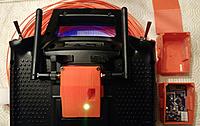
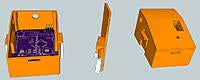
If you have the Banggood ready to use board you can 3D print this case (details here):


Multiprotocol source can be compiled using the Arduino IDE.
The currently supported Arduino version is 1.6.10.
Download the zip file of this repository, unzip it in a folder, navigate to the Multiprotocol directory and then click on Multiprotocol.ino. The Arduino environment will appear and the Multiprotocol project will be loaded.
_Config.h file must be modified to select which protocols will be available, change protocols/sub_protocols/settings associated with dial for PPM input, different TX channel orders and timing, Telemetry or not, ... This is mandatory since all available protocols will not fit in the ATmega328. You need to pick and choose what you want.
Notes:
It is recommended to use an external programmer like USBASP to upload the code in the Atmega328. The programmer should be set to 3.3V or nothing to not supply any over voltage to the multimodule and avoid any damages.
The dial must be set to 0 before flashing!
From the Arduino environment, you can use this shortcut to compile and upload to the module: Skecth->Upload Using Programmer (Ctrl+Maj+U)
To flash the latest provided hex file under Release, you can use a tool like AVR Burn-O-Mat, set the microcontroller to m328p and flash it.
Use this method only for Arduino Pro Mini boards with bootloader.
Use an external FTDI adapter like this one.
The programmer should be set to 3.3V or nothing to not supply any over voltage to the multimodule and avoid any damages.
From the Arduino environment, you can use Upload button which will compile and upload to the module: Skecth->Upload (Ctrl+U)
To upload the latest provided hex file under Release, you can use a tool like XLoader, set the microcontroller to Atmega328 and upload it.
Use a tool like AVR Burn-O-Mat to set the fuses of the Atmega328 to:
This will make sure your ATMEGA328 is well configured and the global TX ID is not erased at each updates.
Make sure to follow this procedure: press the bind button, apply power and then release it after 1sec. The LED should be blinking fast indicating a bind status and then fixed on when the bind period is over. It's normal that the LED turns off when you press the bind button, this behavior is not controlled by the Atmega328. For serial, the preffered method is to bind via the GUI protocol page.
If your module is always/sometime binding at power up without pressing the button:
You can report your problem using the GitHub issue system or go to the Main thread on RCGROUPS to ask your question. Please provide the following information:
此处可能存在不合适展示的内容,页面不予展示。您可通过相关编辑功能自查并修改。
如您确认内容无涉及 不当用语 / 纯广告导流 / 暴力 / 低俗色情 / 侵权 / 盗版 / 虚假 / 无价值内容或违法国家有关法律法规的内容,可点击提交进行申诉,我们将尽快为您处理。


